Raspberry Pi 3 for the Second Time
Let’s Build a Vehicle
1 Restart the journey!
It’s been 1.5 years since I wrote the Raspberry Pi 3 for the First Time article. I wanted to build a mobile robot (i.e., a small autonomous vehicle) so that I could use Raspberry Pi 3 to control it. I hoped to run some cool algorithm (whatever that is) on it.
I did build a few mobile robots.
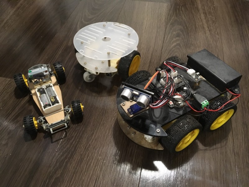
But I was unsure how to control these robots using Raspberry Pi 3.
What device do I need to control the steering angle? How do I send acceleration signals to the motor? I need a reference machine that works to understand the mechanism.
So, I decided to try it for the donkey car. After all, the people who participate in the DIY Robocars Meetup are using it. It shouldn’t be that hard. So I thought.
I was downright wrong about it.
It was not easy. It made me want to give up many times.
Moreover, I made a lot of mistakes. I wanted to blog about the process, but I kept losing track of the build sequence as I went back and forth, fixing the car. I didn’t think writing about a series of unfortunate events was worthwhile.
But I persisted. I pushed myself hard because I wanted to build it on the weekends. Otherwise, I would have lost motivation and stopped working on it.
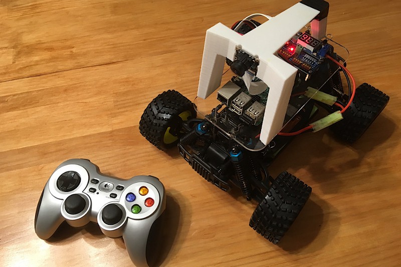
Eventually, I made it thus far to run the donkey car using the Raspberry Pi 3 and the Gamepad remote controller.
This article is the record of the journey.
2 Fix the broken cage!
The first mistake was that I didn’t try building a donkey car earlier. I was indecisive about whether I should do it for over a year. I knew multiple online shops were available, and I could order one with a few clicks.
I thought it would be cheating if I relied on a well-known kit. Moreover, I would miss learning opportunities by just following someone’s instructions.
I was utterly wrong with this.
As you will watch me fail repeatedly in this series, this is a challenging task, and there is tons of learning, especially if you are new to building such a thing.
I ordered a kit from Robocar Store (no affiliation link) simply because they provide an option that sells a package without a Raspberry Pi and micro SD card, both of which I already owned.
It arrived in about ten days from Hong Kong to Japan. I was excited, but my full-time job kept me engaged on weekdays, so I had no time to work on the package.
Every night, after coming home from work, I watched the box and imagined the fun of building the car on the weekend.
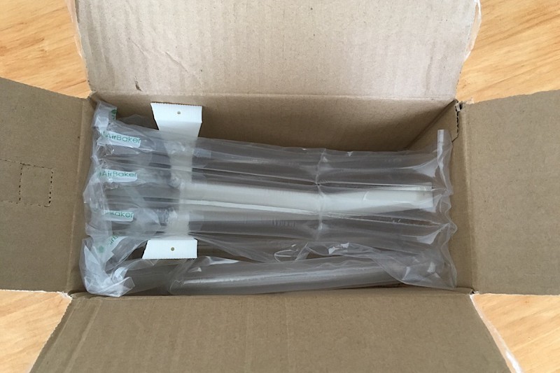
Four days later, on a Saturday morning, I opened the box with my heart pounding.
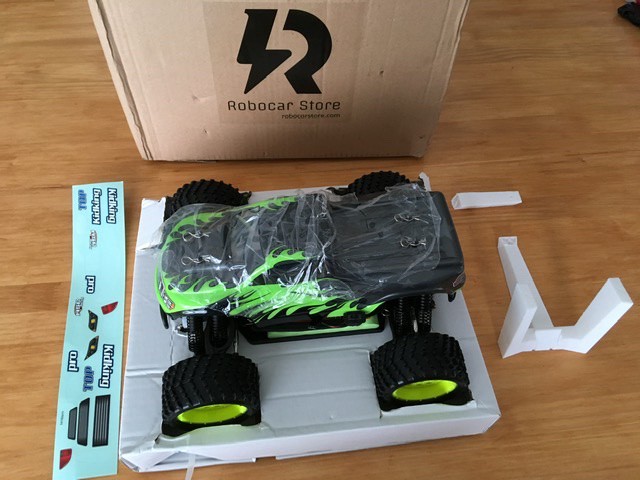
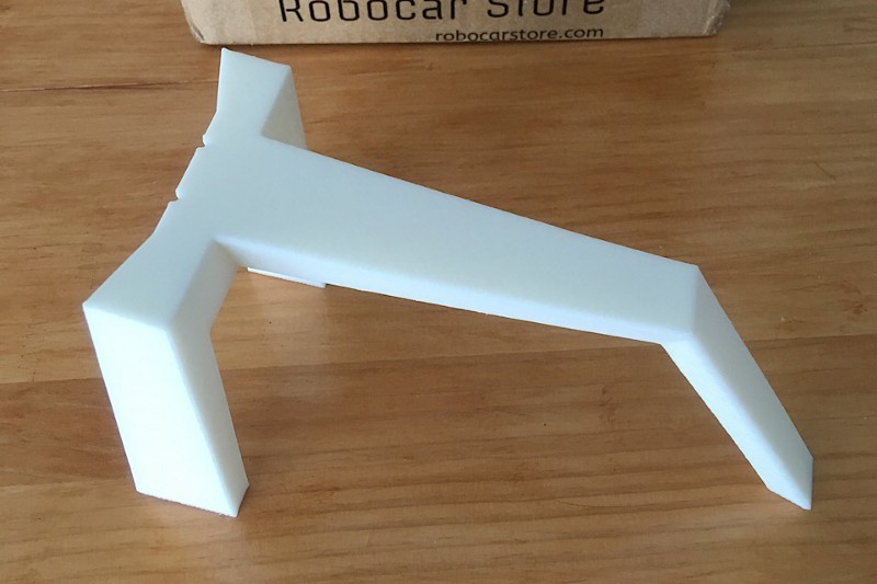
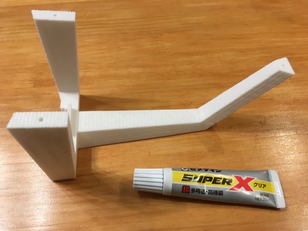
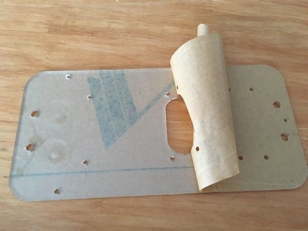
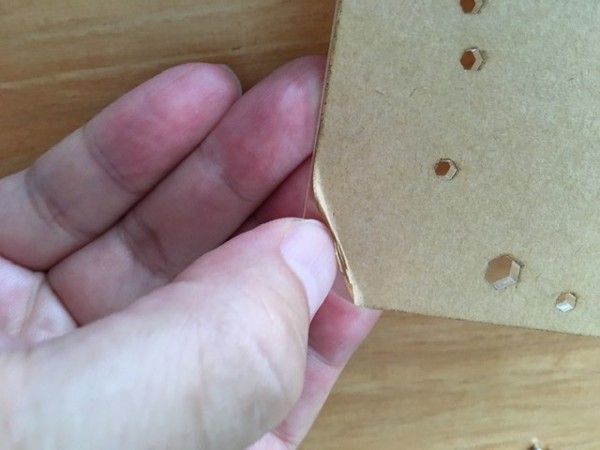
I stared at the 3D-printed cage in two parts for a moment.
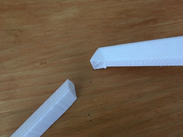
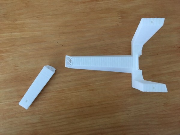
Yes, I saw it right. It’s broken. The breakage must have happened somewhere between Hong Kong and Japan.
Calm down. It must have come with a warranty.
The kit included a paper that says:
If any part is missing or malfunctioning, please contact us within three days of receipt, and we’ll arrange to reship or exchange to you.
Was I too late to notice the problem? I should’ve checked the product as soon as it arrived. My heart was pounding strange beats.
Why didn’t I order from a shop in Japan? If a part is broken or missing, they can send me a replacement faster. Was it worth trying to save the cost of Raspberry Pi 3 and micro SD card by ordering from overseas? Why didn’t I consider the worst-case scenario?
I emailed the Robocar store with some images of the broken parts. I got a reply within an hour, and they promised to send me a new one. What a relief!
But I didn’t want to wait another week to build the donkey car. I should strike while my motivation is hot.
So, I applied glue to the disconnected surfaces of the 3D-printed cage and patched it up with vinyl tape.
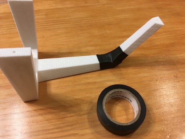
I was proud that I was able to do that. I just needed to be resourceful to deal with any issue and move on.
Let’s open up this little monster to conduct an operation, shall we?
3 List up all the parts!
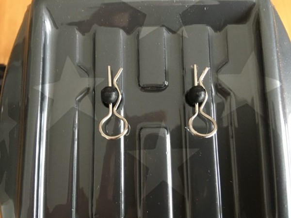
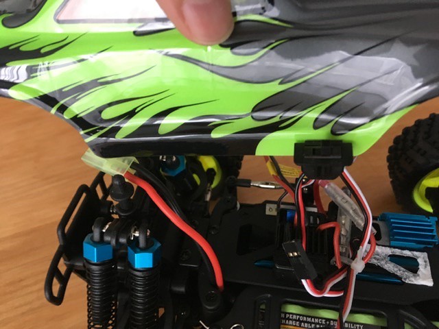
I removed four clips, two from the front and two from the back.
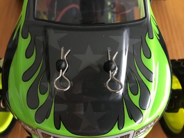
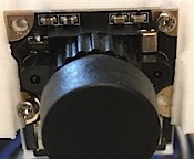
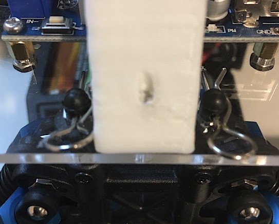
I slowly and carefully opened the cover.

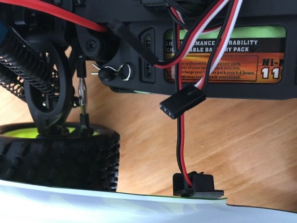
When I finished opening the cover, I found a small switch attached.
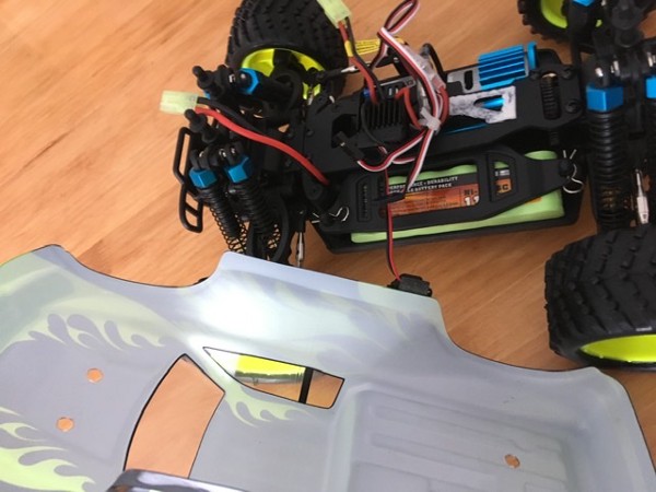

I had no idea what the use of such a switch was. For that matter, I didn’t know much about anything that came in this package.
I thought I should at least know the names of all those parts and devices.
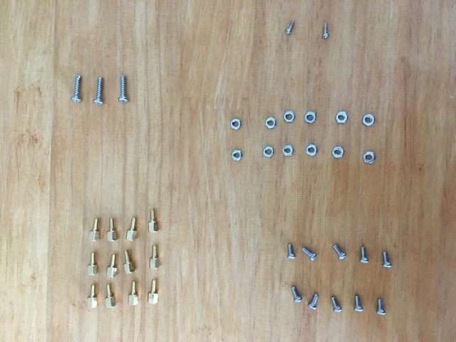
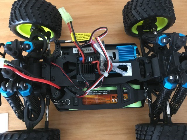
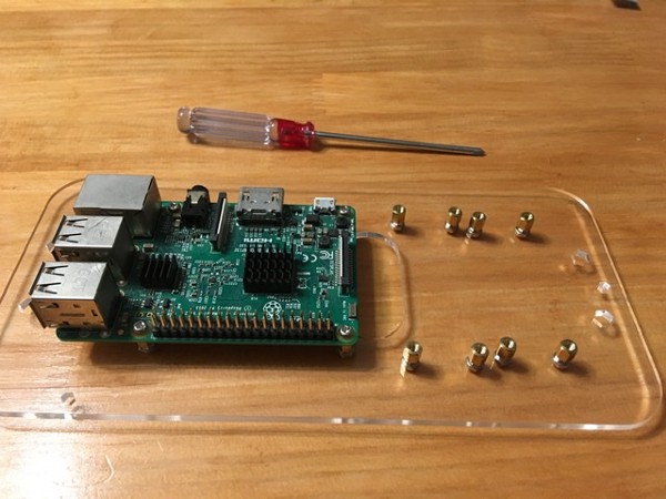
There were a lot of screws and devices in the part list. So, I took them all out and ensured I had them all.
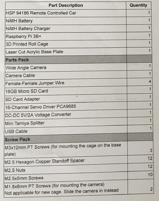
My order didn’t include Raspberry Pi, SD card, and SD card adapter, as I already had them. Otherwise, everything was there.
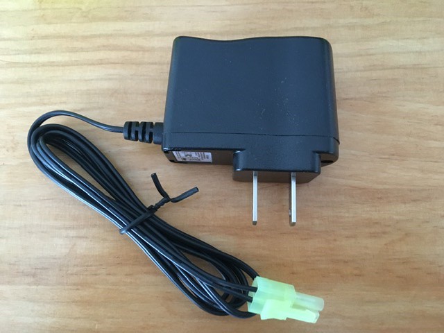
NiMH Battery and NiMH Battery Charger

3D Printed Roll Cage

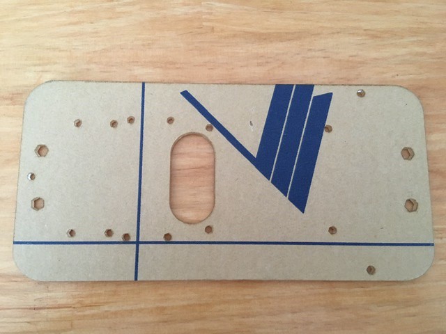
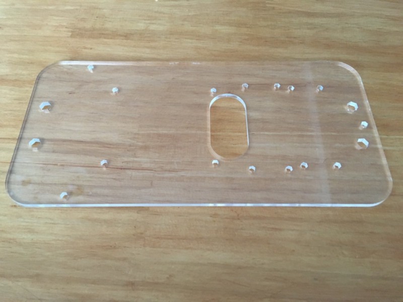
Laser Cut Acrylic Base Plate
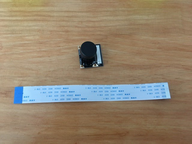
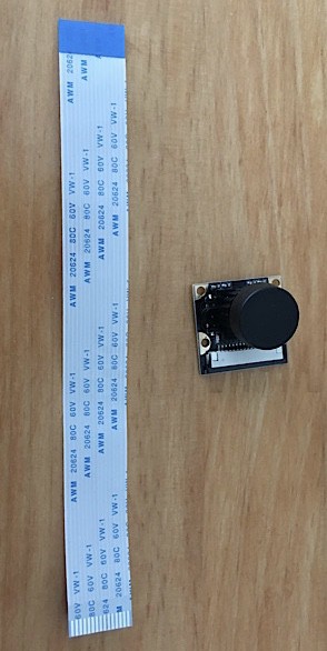
Wide Angle Camera and Camera Cable
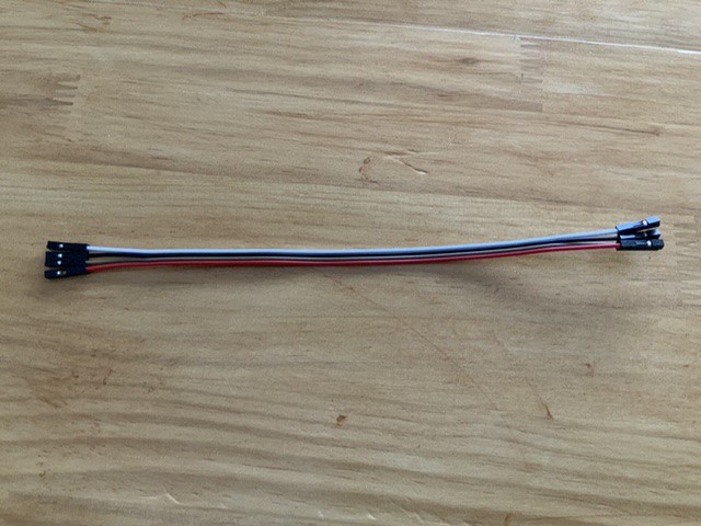
Female-Female Jumper Wire
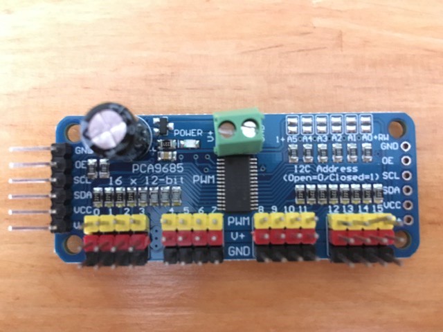
16-Channel Servo Driver PCA9685
DC-DC 5V/2A Voltage Converter

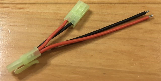
Mini Tamiya Splitter
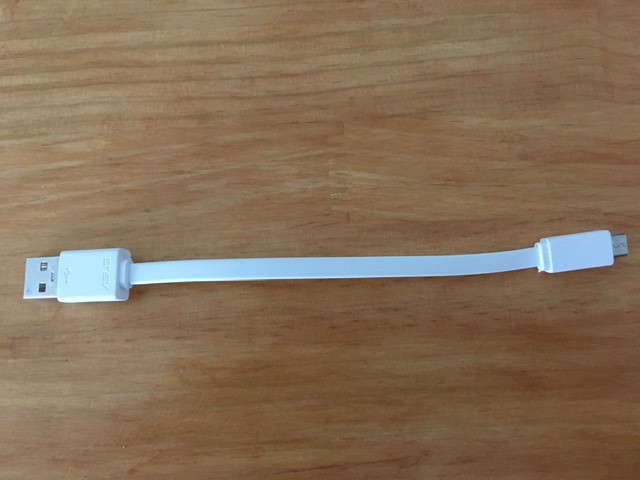
USB cable
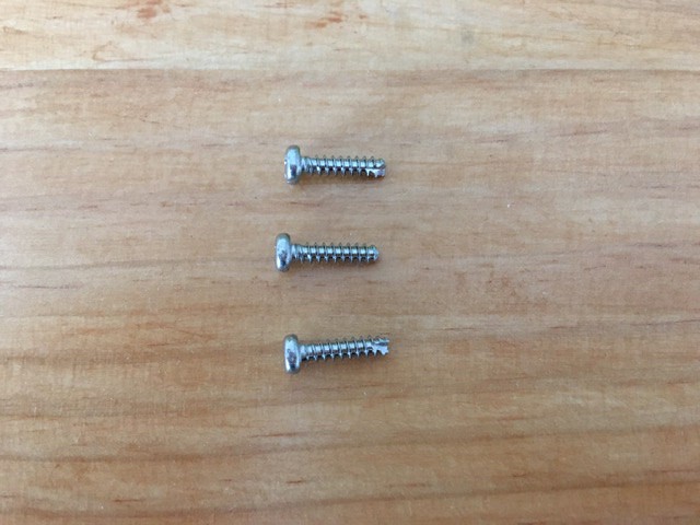
M3x12mm PT Screws (3)
M2.5 Hexagon Copper Standoff Spacer (12)
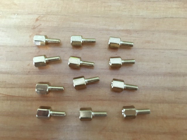
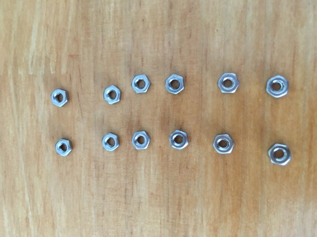
M2.5 Nuts (12)
M2 5x5mm Screws (10)

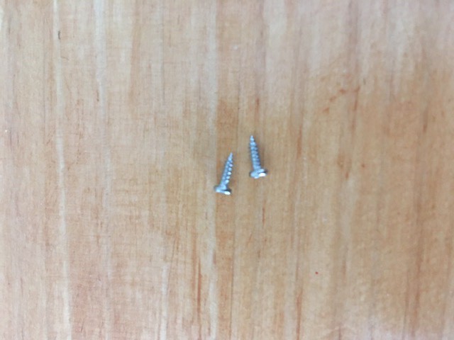
M1.8x6mm PT Screws (2)
Checking all the part names was tedious, but it was perfect. As I followed the build instructions from https://docs.robocarstore.com, knowing where each part was made me work very efficiently.
So, I did very well in this episode. Right?
Yes, except that I missed a small thing that made me waste about 30 minutes. I will talk about that a few sections down the line.
4 Attach Raspberry Pi on the base plate!
Let’s go back to where I was.
I removed four clips, two from the front and two from the back.


I didn’t realize that time, but I needed those clips later to fix the base plate on the car, which holds the Raspberry Pi. So, if you happen to follow this, you will need to keep them aside.
Next, I slowly and carefully opened the cover.
When I finished opening the cover, I found a small switch attached.

I had no idea what the use of such a switch was.
But I knew I wouldn’t use the cover, so I removed the switch.
I saw white stuff in the middle, which turned out to be where the RC receiver was.
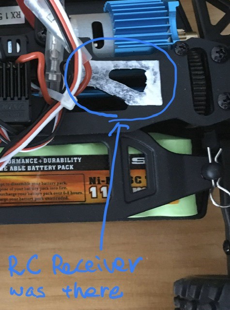
The shop removed it as robocars don’t need it. Hence, not included in the kit.
From here, I followed the instructions from https://docs.robocarstore.com, which originates from http://docs.donkeycar.com, but the contents are specifically for the Donkey Car Kit from the Robocar store.
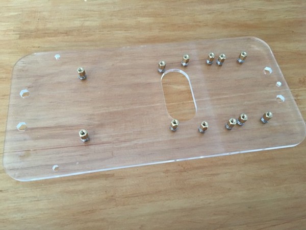
First, I started peeling off the protection sheet from the base plate.
According to the documentation, many people missed that they needed to peel off the protection. It would be best not to miss it because the base plate has a beautiful transparent body.
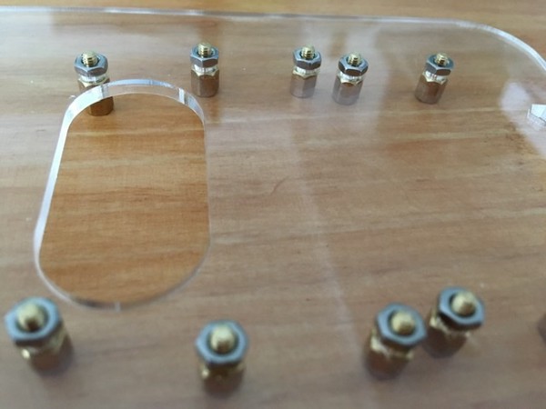
Next, I mounted the M2.5 Hexagon Copper Standoff Spacer and M2.5 Nuts to the base plate.

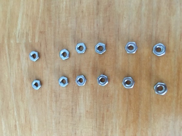
It took no time to do this, thanks to well-prepared nuts and bolts.
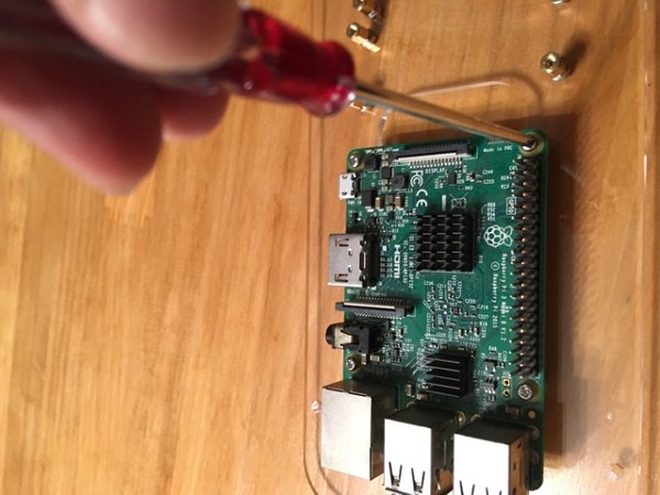
After that, I attached Raspberry Pi to the base plate using the M2 5x5mm Screws.
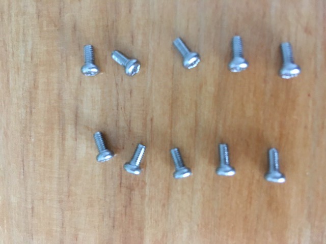
You need four skews to attach Raspberry Pi to the base plate.
Then, I attached 16-Channel Servo Driver PCA9685 to the base plate using the same M2 5x5mm Screws. Again, you need to use four skews for the servo driver.

Finally, I again attached the DC-DC 5V/2A Voltage Converter to the base plate using the same M2 5x5mm Screws. But there are only two of the M2 5x5mm Screws left. Don’t I need four screws?

DC-DC 5V/2A Voltage Converter has four holes for screws, but only two can fit the M2 5x5mm Screws. As it turns out, the other two don’t need any screws. Who would know that!?
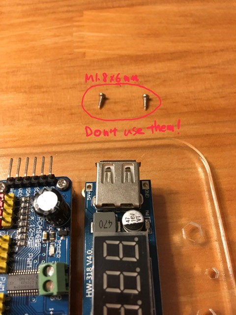
I spent 10–15 minutes trying to use M1.8x6mm PT Screws for the two holes, but they don’t fit. So, it would be best if you did not try that.
They are for electric power. You can see the texts near the holes that read “5V+” and “GND” (Ground).
By this time, the base plate had everything on it.
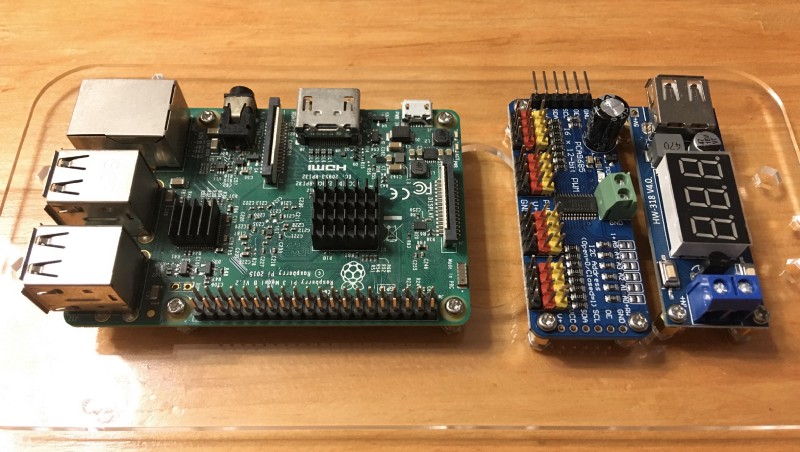
Let’s wire them up!
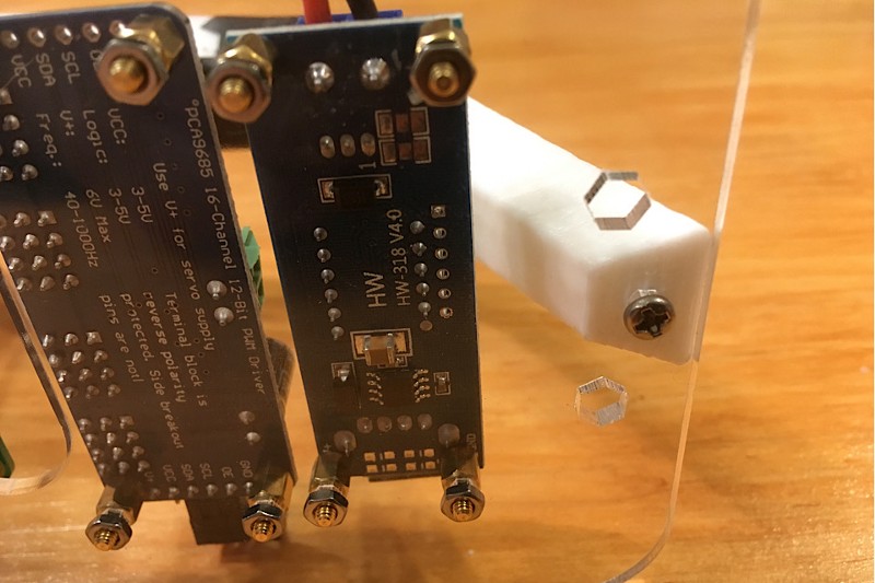
5 Wire up the Servo Driver!
But wait. What are these small blue boards (the servo driver and the voltage converter) doing?
5.1 The servo driver
First, we are connecting the servo driver to Raspberry Pi. The servo driver in this kit is the 16-Channel Servo Driver PCA9685.
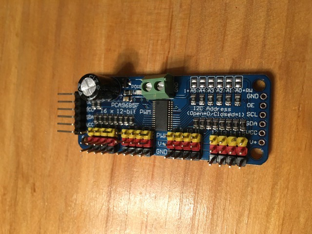
A servo driver is a device that can control the servo motors. The 16-Channel Servo Driver PCA9685 can handle up to 16 servo motors.
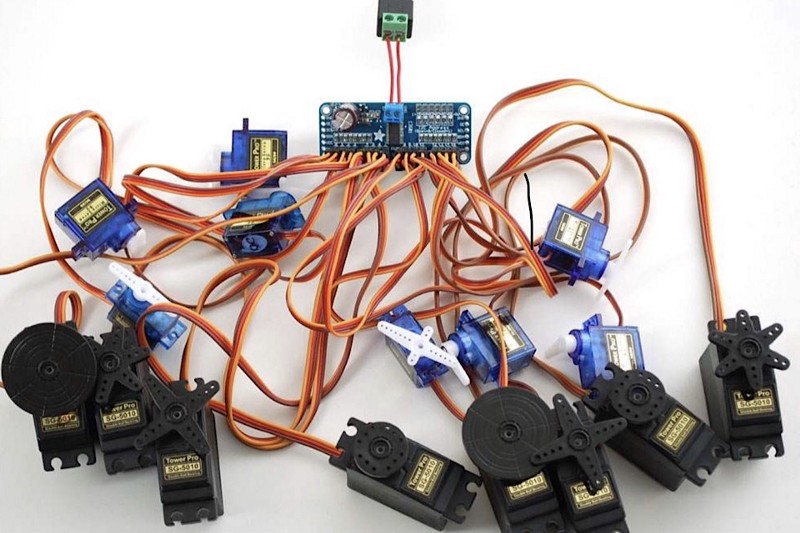
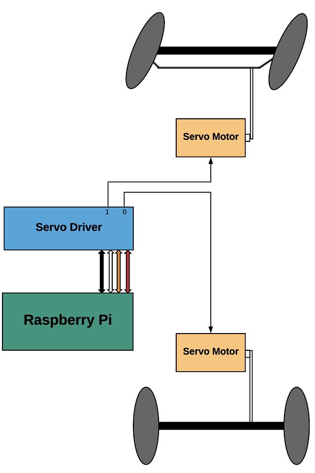
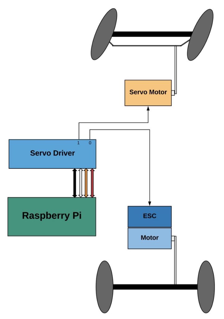
We have two servo motors on the car: one for controlling the wheel angle and the other for speed control.
The speed controller is not strictly a servo motor but can accept the same signals from the servo driver. So, from the servo driver’s point of view, it appears as a servo motor. I will explain more details in the next episode.
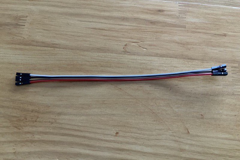
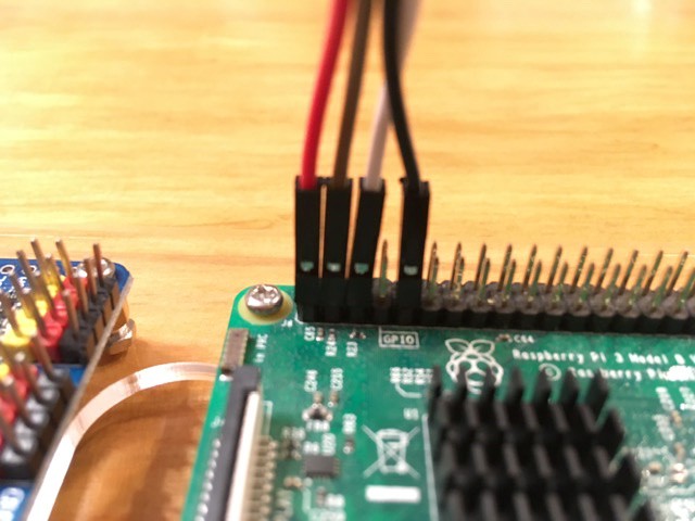
We use the Female-Female Jumper Wire to connect Rasberry Pi to the servo driver so that a program on Rasberry Pi (like the donkey car software) can control multiple servo motors.
So, what are those four wires connecting?
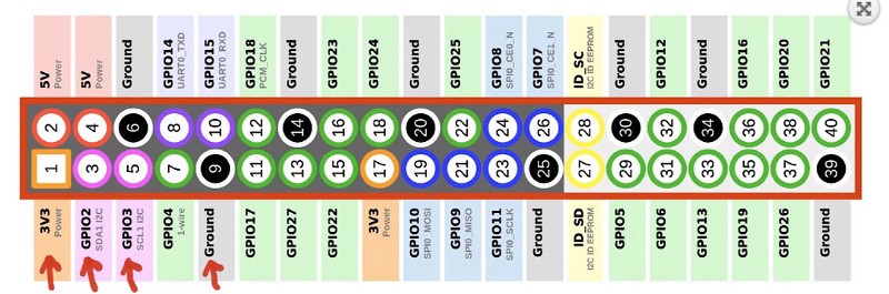
5.2 Raspberry Pi’s GPIO pins
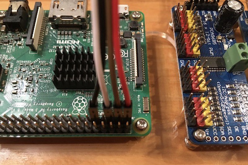
Raspberry Pi 3 has 40 GPIO (General Purpose Input Output) pins to communicate with other devices.
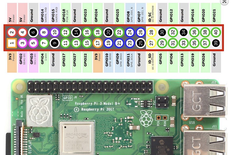
We use the 3v3 (Power), GPIO2 (SDA1 I2C), GPIO3 (SCL1 I2C), and Ground pins. Power and Ground are for electricity supply. SDA and SCL are for I2C communications — more on this later.
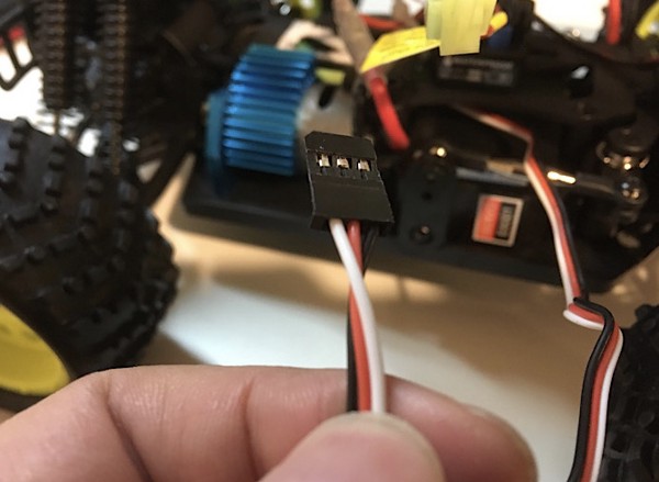
5.3 The cable color scheme
When I connected the four cables to Raspberry Pi, I didn’t know which color should go to which pin.
As it turned out, there is no standard for the cable colors except for a dark color (i.e., black), typically used for the ground.
For the servo driver, you should ensure the ground goes to the ground, SDA goes to SDA, SCL goes to SCL, and 3v3 goes to VCC (power) on the servo driver.
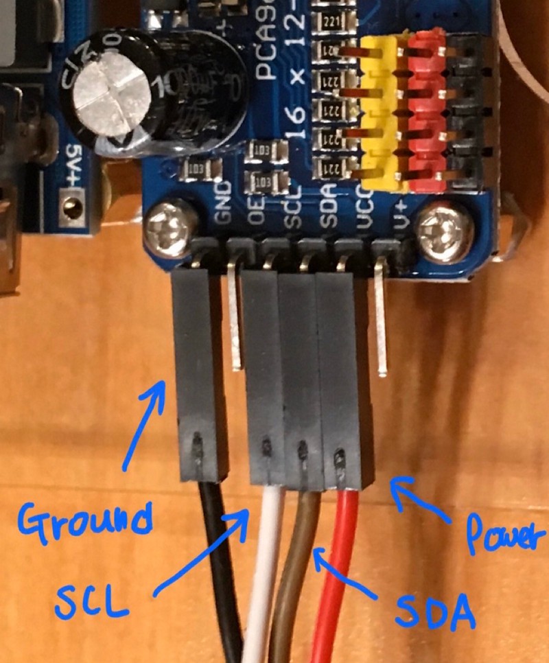
The cable colors help you to match the corresponding pins.
5.4 About I2C
SCL stands for ”serial clock”, and SDA for ”serial data”. These terms are part of the I2C bus specification.
Quoting from the I2C Info website:
A bus means specification for the connections, protocol, formats, addresses and procedures that define the rules on the bus.
It allows devices to communicate with each other as long as they follow the rules defined in the I2C specificities.
As per Wikipedia, I2C stands for “Inter-Integrated Circuit” (whatever that means), pronounced as “I-Two-C” or “I-I-C”. But I heard someone says “I-Squared-C”. So, be aware.
The thing is that it uses only two wires to communicate with multiple devices. We already know what those two wires are. They are SCL and SDA.
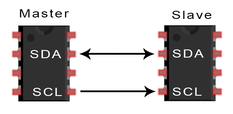
Both Raspberry Pi and the 16-Channel Servo Driver PCA9685 support I2C to communicate. As such, we need to connect and match the pins for the same purpose.
As a metaphor, you can think of a USB-C cable that allows devices to communicate with each other as long as both devices support the USB-C bus.
I2C is unique in that a slow device can communicate with a faster device without slowing down the faster one by synchronizing the timing using the clock signals via the SCL line.
For more details, I listed links in the reference section at the end of this episode.
One more thing: I will need to connect two servo motors to the servo driver since we want to control them, but I will come to that after attaching the base plate to the car body.
Next, look at the other blue board: DC-DC 5V/2A Voltage Converter.
6 Connect the Voltage Converter!
Let’s wire the DC-DC 5V/2A Voltage Converter!
It has a USB port through which you can supply electricity to your Rasberry Pi.
DC vs. AC
DC stands for Direct Current as opposed to AC, which stands for Alternating Current. AC is suitable for long-distance transmissions, which is why electricity from the house wall electricity socket is AC.
A battery uses chemical reactions to generate electricity, which can only be DC. Motors and Raspberry Pi also use DC.
A DC-DC voltage converter takes DC electricity in one voltage and outputs DC electricity in a different voltage.
The DC-DC 5V/2A Voltage Converter converts an input of 4.5–40V into a stable 5V 2A output.
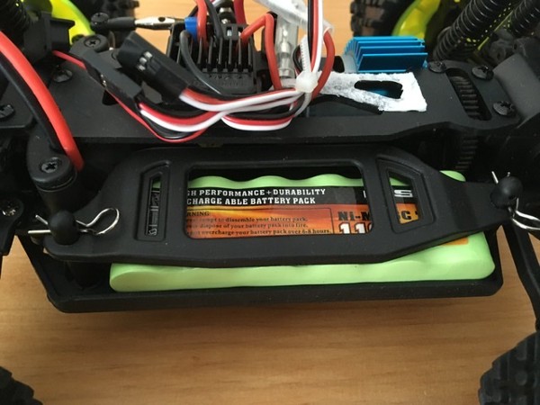
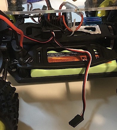
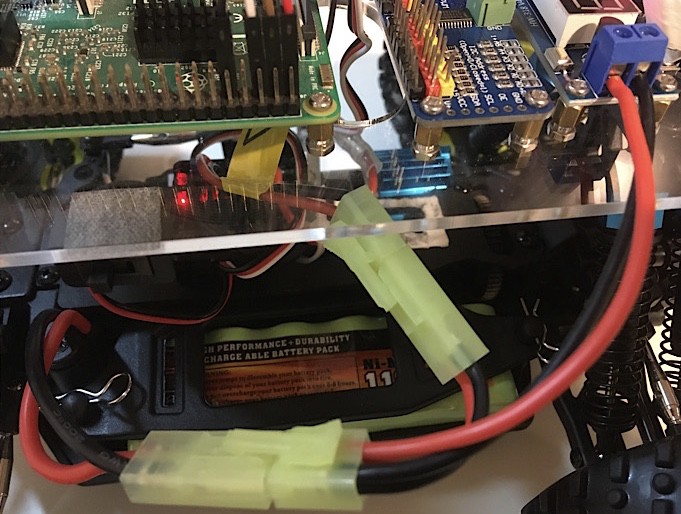
The battery
The battery is secured on the car’s body. We can take it out to see the whole body.
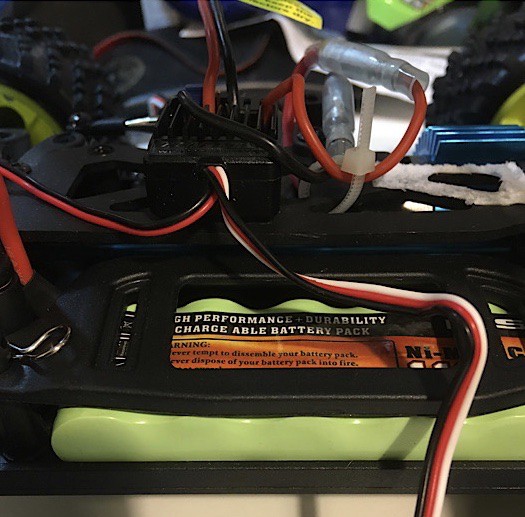
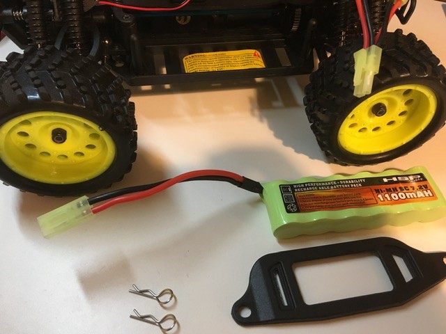
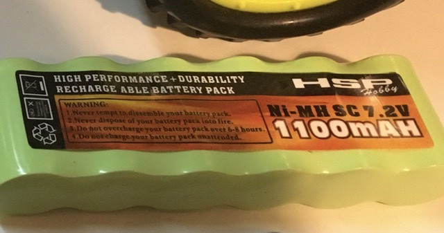
It says, “HSP Ni-MH SC 7.2V 1100 mAh”. The voltage converter can handle 7.2V, within the 4.5–40V input range. That should be obvious, as they came in the same package, but it’s good to know.
Warning
There is a yellow sticker that has a warning.
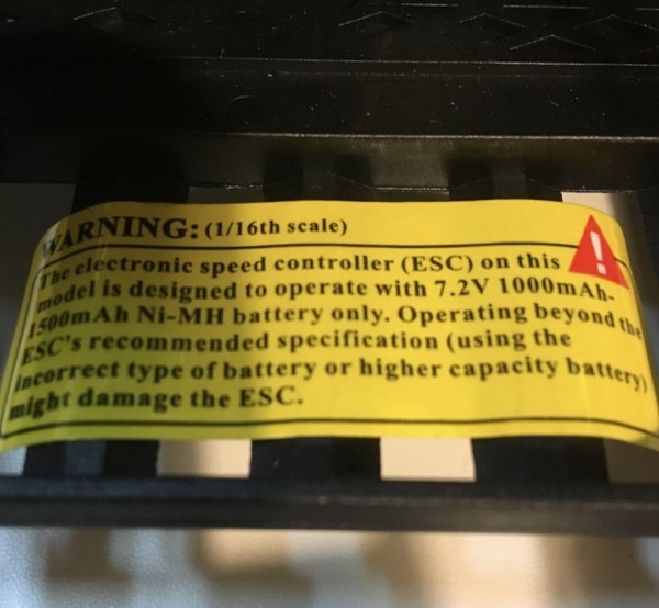
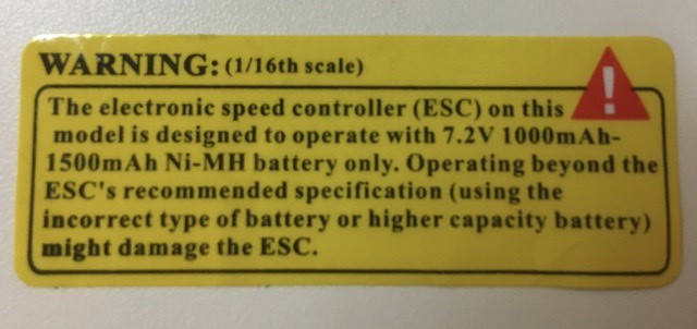
The electronic speed controller (ESC) on this model is designed to operate with 7.2V 1000 m Ah — 1500 m Ah No-MH battery only. Operating beyond the ESC’s recommended specification (using the incorrect type of battery or higher capacity battery) might damage the ESC.
Since our battery came in the package, there is no problem here. But if you plan to replace the battery, you must pay attention to it.
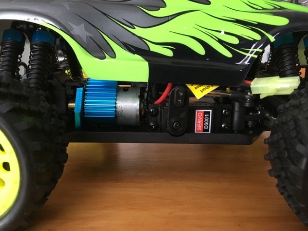
ESC
The electronic speed controller (ESC) talks to the DC motor to adjust the car’s speed.
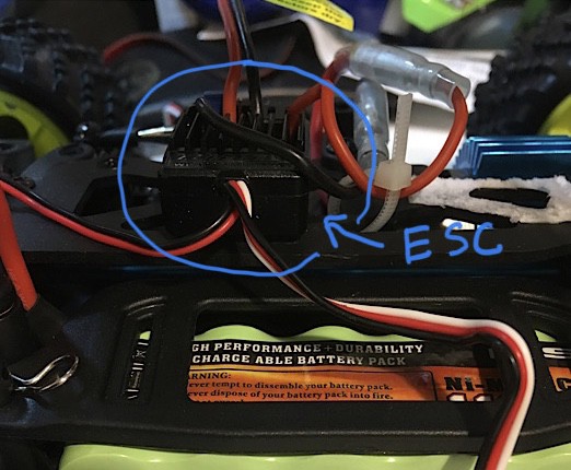
ESC can accept signals from the servo driver so it appears as a servo motor from the servo driver’s point of view.
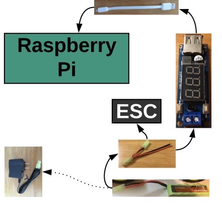
I revised the diagram from the last episode to clarify the point.
Mini Tamiya Splitter
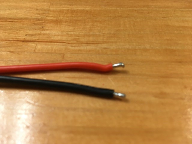
We use the Mini Tamiya Splitter to connect the battery to the voltage converter and to ESC.
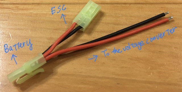
The cable exposes the metal parts which should go into the power inputs of the voltage converter.
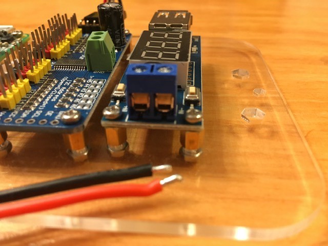
So, I loosened the power inputs.
But the metal parts were quite thick and wouldn’t go inside. I tried loosening more. However, it was already fully opened.
After some struggle, I thought, “Why don’t I just flatten them?” So, I did.
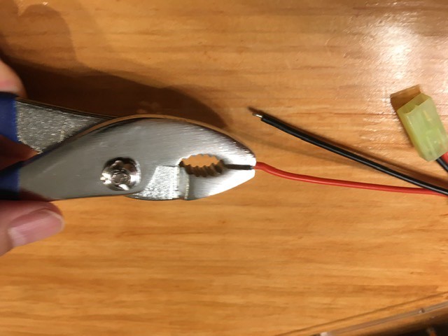
Then, they fit perfectly into the power inputs. I tightened the holes with a screwdriver, which were nicely fixed.
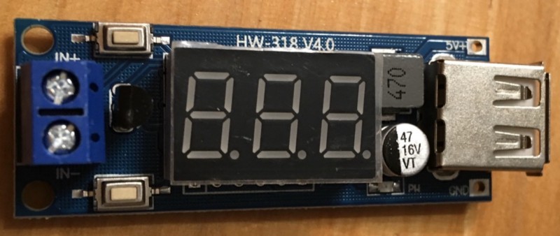
DC-DC 5V/2A Voltage Converter
The voltage converter has two types of outputs: the USB output and the two small holes (output + and -) which I was sadly trying to insert a screw two episodes ago.
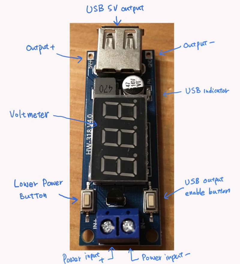
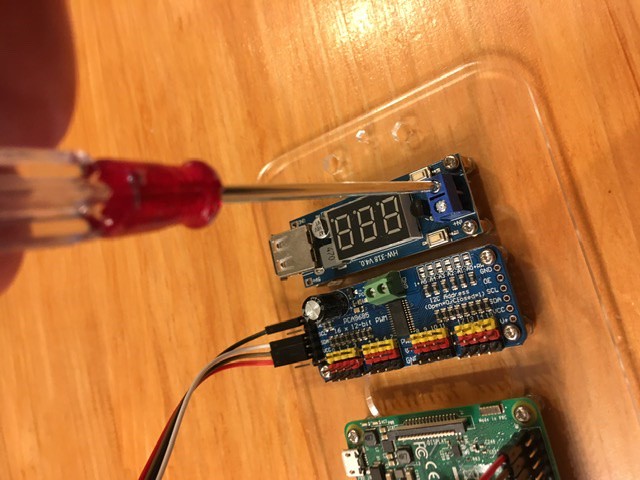
As we use the USB output, the USB output enables the button should be pressed, and the USB indicator should light up when there is electricity.
The lower power button puts the voltage converter into standby mode, effectively turning off the device. The USB output will stop supplying electricity.
In my case, the USB output enables button was on, and the lower power button was off from the box, which is probably the factory default. So I didn’t need to change anything on the voltage converter. You may want to check these settings if your USB output isn’t working.
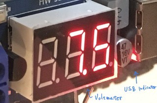
The voltmeter displays incoming voltage, which varies depending on how much the battery is charged. Although it should be around 7.2V, it can go above 8V when the battery is fully charged. The output of the voltage converter is 5V 2A regardless.
If the voltmeter shows a low number, you can charge the battery with the NiMH Battery Charger.
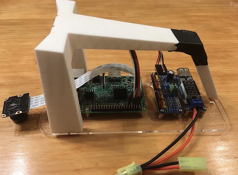
The whole picture
Later, when the base plate is fixed on the car, I will convert the whole thing as shown in the below image.
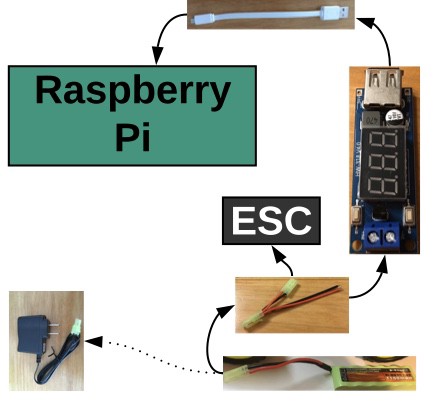
Well, we’re still missing the camera in the picture. Let’s work on that in the next section.
Last but not least, be careful when dealing with electricity. Don’t touch any electrical parts.
7 Slide down the wide-angle camera!
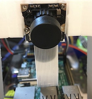
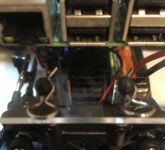
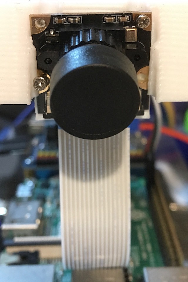
There are two problems in the above pictures. Can you tell me what they are?
If not, you’ll be glad that you are reading this article.
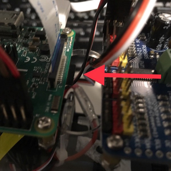
Raspberry Pi has built-in support for camera modules. As such, it should be easy to plug the cable into the camera and connect it to Raspberry Pi.
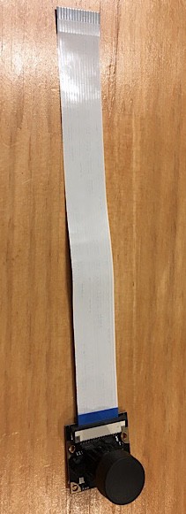
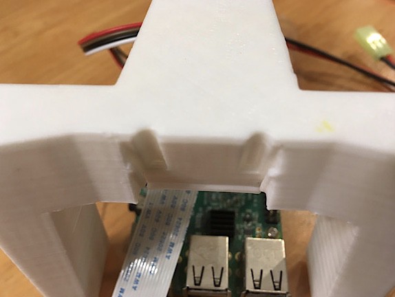
So, I connected the Wide Angle Camera and Camera Cable. The first problem was here. I inserted the Camera Cable incorrectly. I should have flipped the cable around.
Without noticing the problem, I went ahead and connected the Camera Cable to Raspberry Pi — again incorrectly. This time, it’s connected to the wrong place.
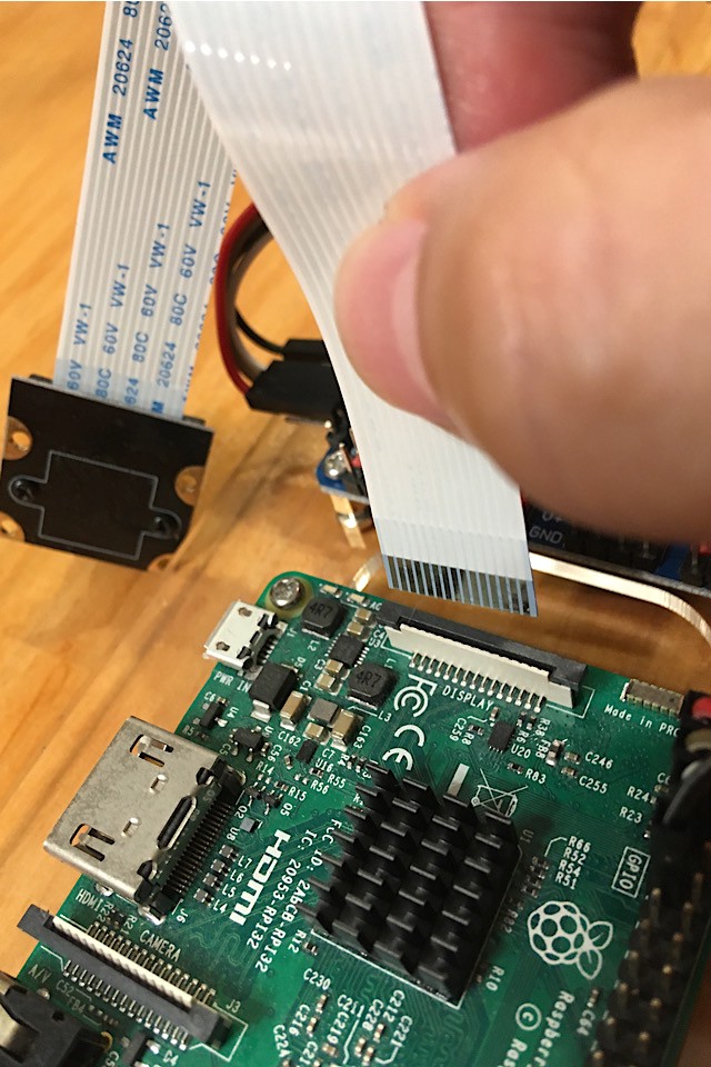
I inserted the cable to the DSI, not the camera module port!
So, please do not refer to the above images when you work on the camera module.
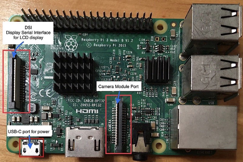
FYI — there is a detailed description of how to connect the camera module on the Raspberry Pi website.
[embed]https://projects.raspberrypi.org/en/projects/getting-started-with-picamera[/embed]
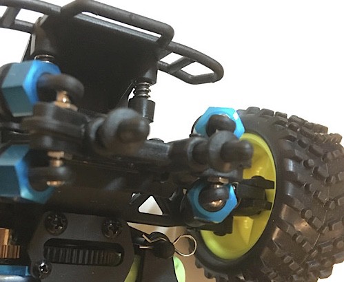
Without realizing my mistakes, I attached the 3D Printed Roll Cage to the base plate.
Again, the camera module Cable was still in the wrong place.
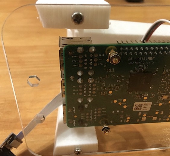
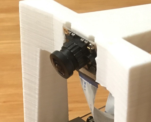
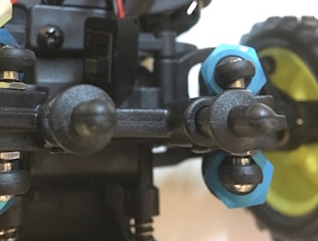
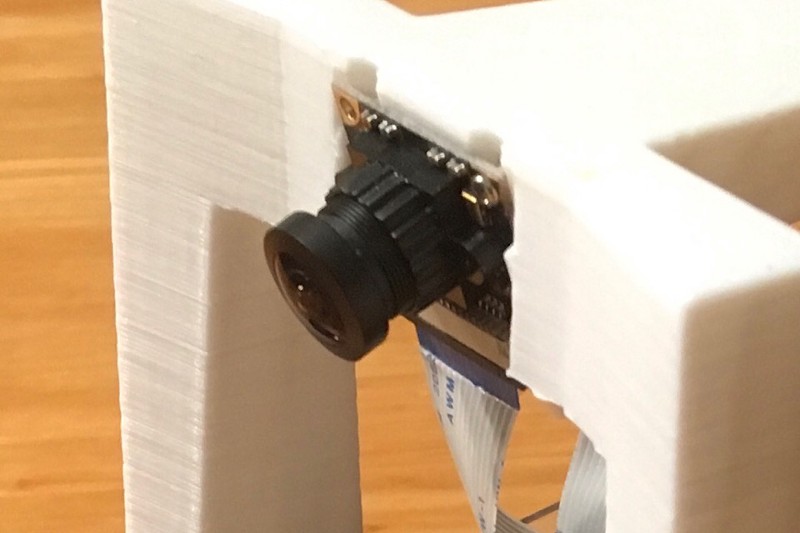
Then, I slid the Wide Angle Camera into the cage.
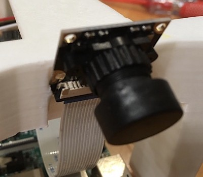
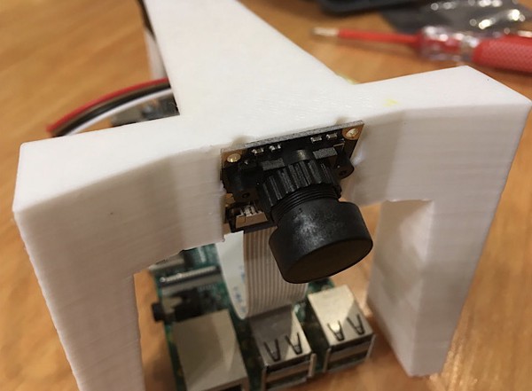
The Camera sits there perfectly. It didn’t seem necessary to use the M1.8x6mm PT Screws, but I did anyway, which was the wrong thing to do.
Even worse, it took quite some time to do it because the surface of the slit area is not flat at all, as you can see from the images.
Later on, I noticed that the description in the part list says it clearly.
M1.8x6mm PT Screws (for mounting the camera)
Not applicable for the new cage. Slide the camera in instead.
If you’ve read the earlier episode, I checked all the parts and laid them out neatly so that I could find them efficiently. That was a great thing to do, except that I didn’t go back to the part list after that and missed the description completely.
Without realizing all those mistakes, I attached the base plate to the car using the four clips we put aside in the earlier episode.
After this, I connected ESC and the servo motor to the servo controller so that Raspberry Pi could control them.
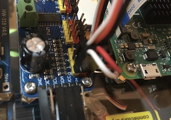
ESC goes to channel 0, and the servo motor goes to channel 1.

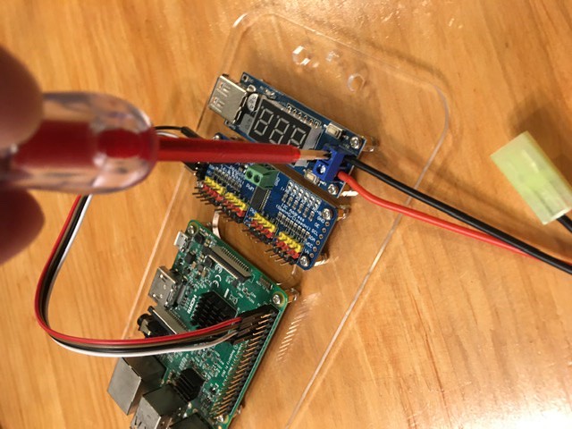
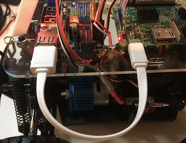
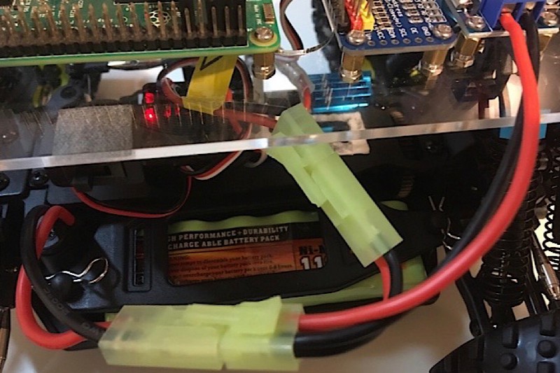
Then, I connected all the other cables: the voltage converter to Raspberry Pi via the USB cable and the battery to ESC, and the voltage converter:
Be careful with electricity when you do this. The battery will send electricity to the parts:
The voltmeter lit up the input voltage, which reads 7.4V. Everything looked ok to me, as I didn’t notice the camera cable issue yet.
So, I said to myself — now that the hardware is set up, I only need to install the donkey car software on the micro SD card and slot that into Raspberry Pi!
8 Install the donkey car software!
I finished building the hardware. I just needed to install the donkey car software on the micro SD card and slot that into Raspberry Pi.
But first, I had to install the Raspbian OS.
Raspbian OS
Two years ago, I installed Raspbian on Raspberry Pi. So, I knew what to do.
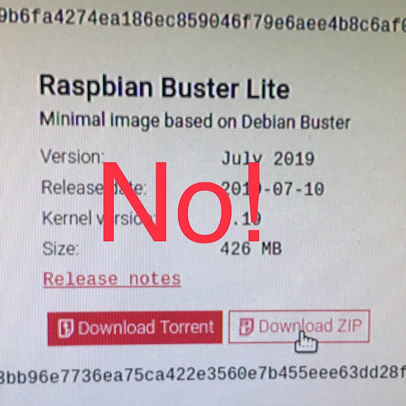
I went to the Raspberry Pi website and downloaded Raspbian Buster — the latest version.
And this was the wrong thing to do.
The donkey car doesn’t support Raspbian Buster. It supports the previous version, Raspbian Stretch. When I was working on the vehicle, Raspbian Buster had only been released less than a month ago.
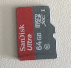
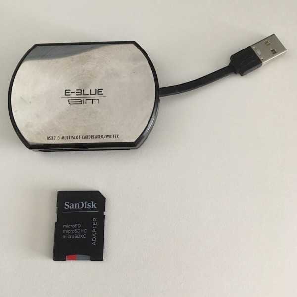
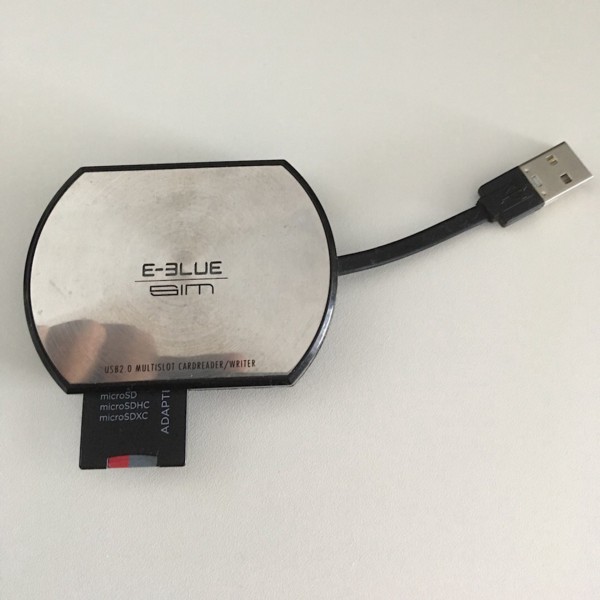
So, I downloaded Raspbian Stretch and followed instructions to copy the OS onto the micro SD card, which requires an SD card adapter.
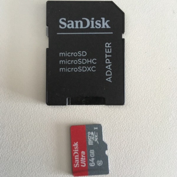
Also, you’ll need an SD card reader (built-in or external).
What’s wrong with my SD card?
I found an SD card reader from a box of junk cables at home, so I can’t throw away things. Even though they may not spark joy, junk could be helpful one day.
I connected the SD card reader to my Linux PC, but it did not recognize the SD card for some reason.
I searched for a solution on the internet for a while but couldn’t find a way to read the SD card or even format it.
I tried it on my Mac mini as well but in vain. I started suspecting something wrong with the SD card reader, but that SD card reader was the only one I could find at home.
Should I go out and buy a new SD card reader? But how would I know that would fix the problem?
I suddenly remembered that my wife’s PC had Windows 10 and a built-in SD card reader. I borrowed it from her and inserted the SD card. I could access it!
I formatted the card, thanked my wife with a big smile, and returned to my Linux PC. Yes, I was able to copy Raspbian Stretch to it!
So, that was not a problem with the SD card reader. Then, what was it? I have no idea why it worked until this date.
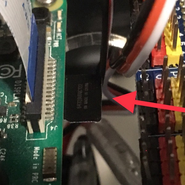
Boot up the Raspbian
I pushed the SD card into the Raspberry Pi’s SD card reader. It’s underneath and a bit hard to handle.
I connected the battery cable to Tamiya Mini Splitter, connecting to the DC-DC voltage converter and ESC.
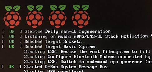
The Raspbian OS started booting up.
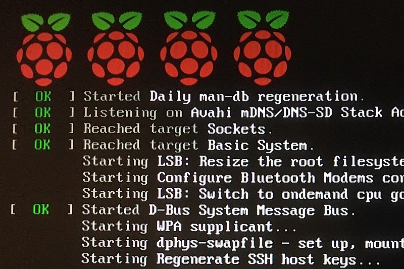
I had a small monitor supporting HDMI to see the boot sequence. Once the OS boots up well, you can remotely access it. So, a local monitor is not a must. But a monitor would be much more convenient as you can watch the boot sequence.
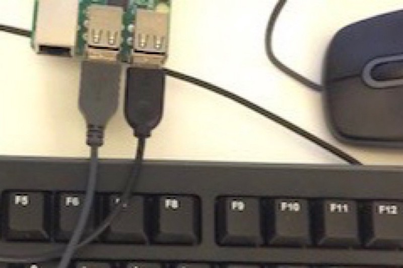
For that matter, I had a USB keyboard and mouse connected to Raspberry Pi.
In more detail, I covered similar stuff in Raspberry Pi 3 for the First Time.
I updated and upgraded the OS.
sudo apt-get update
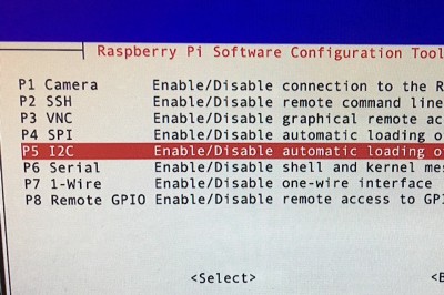
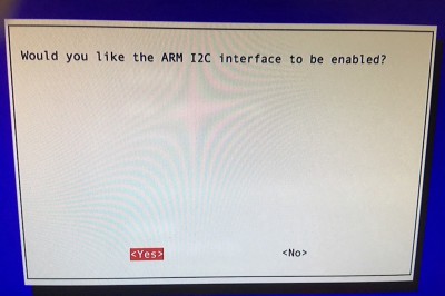
sudo apt-get upgradeThen, I enabled a few interfaces using the command:
sudo raspi-configI enabled I12C.
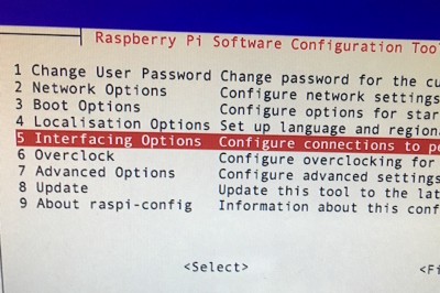
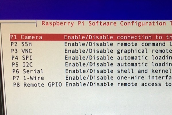
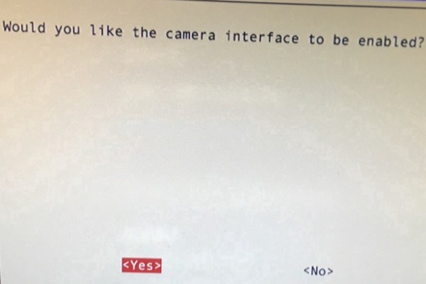
I enabled the camera support.
I finished the OS setup without any problems.
Donkey car software installation
The donkey car software uses behavior cloning to control the car. As such, we need to train the machine learning model, which requires a lot of computing resources. So, the training is done on a PC (i.e., Linux machine), ideally with some GPU.
For training, we need to collect data which consists of camera image frames, speed levels, and steering angles. As such, we need to manually and remotely drive the car to collect data.
So, installing the donkey car software allows me to drive the car using a remote controller.
I installed all the dependencies and cloned the Donkey software.
git clone https://github.com/autorope/donkeycar
cd donkeycar
pip install -e .[pi]
I will not put all other details here as you can follow the instructions to set up the donkey car application on Raspbian and the training environment on a host PC.
All in all, I was ready to drive the car.
9 Remote control the robocar!
It is the final episode of the series. Thank you for reading all along. I hope you’ll enjoy this little ending too.
What’s wrong with my camera module?
When I started the donkey car application, I got an error saying it didn’t recognize the camera.
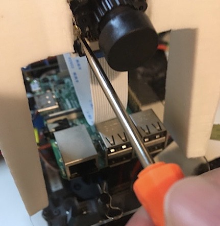
I looked at the camera and immediately realized I had to remove the camera cap. So I did that.
Still, the same error occurred.
If you’ve read the penultimate episode, you know the problem. I connected the camera cable to the wrong place, and the camera cable should be twisted as well.
I realized this while watching Donkey Car Assembly Video.
I fixed the camera cable connection, and the camera error had gone.
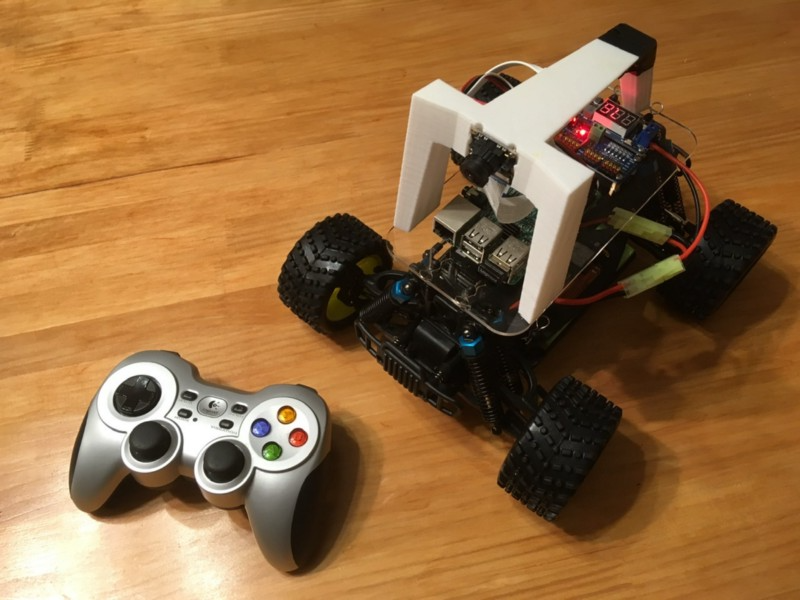
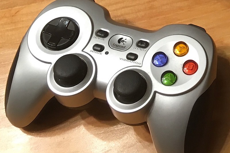
Remote controller
The remote controller is not part of the package. It’s one of those things I bought and forgotten about. It’s Logitech F710 Wireless Gamepad with a Bluetooth wireless receiver that you can plug into the Raspberry Pi’s USB port.
I grabbed my remote controller and controlled the wheels, which moved toward left and right as I wished. Great!
But it didn’t move forward. It didn’t go back, either. Why?
Soon, I realized it was because of the little switch for ESC.
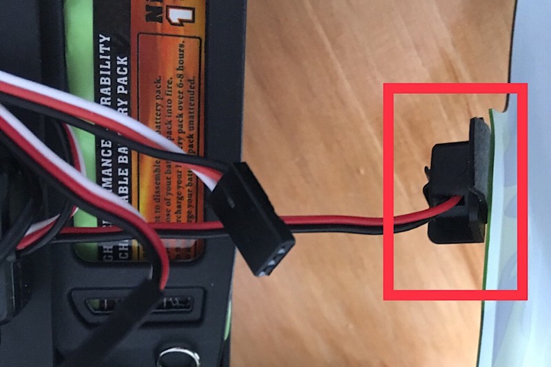
Until now, I didn’t realize the use of this little switch.
I switched on ESC, and I could remote control the car around in my place.
Such a wonderful feeling!
10 Conclusion
The journey ends here. It was only a two-day adventure, but I learned a ton and was delighted with the result.
Now, I have a neat little hardware platform to experiment with whatever algorithm I want. I succeeded!
One last thing: the replacement for the 3D printed cage arrived a week after I contacted the robocar store. It came in a well-protected box. So, I now have a spare 3D-printed cage. 😊👍